
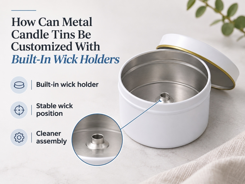
How Can Metal Candle Tins Be Customized With Built-In Wick Holders?
For metal candle tins with a built-in wick-holding structure, the bottom design must securely hold the wick assembly without compromising the container’s stability, wax capacity, or the finished product’s appearance. To meet these requirements, we evaluate the container’s diameter, the number of wicks, the dimensions of the retaining components, and the bottom geometry before developing the mold to ensure compliance with the above criteria. Depending on specific application needs, solutions may include: stamping positioning seats into the metal base, using a separate metal wick retainer, or combining both approaches. The final design must also be compatible with the customer’s filling process and validated using the actual wax and wick combination intended for use.
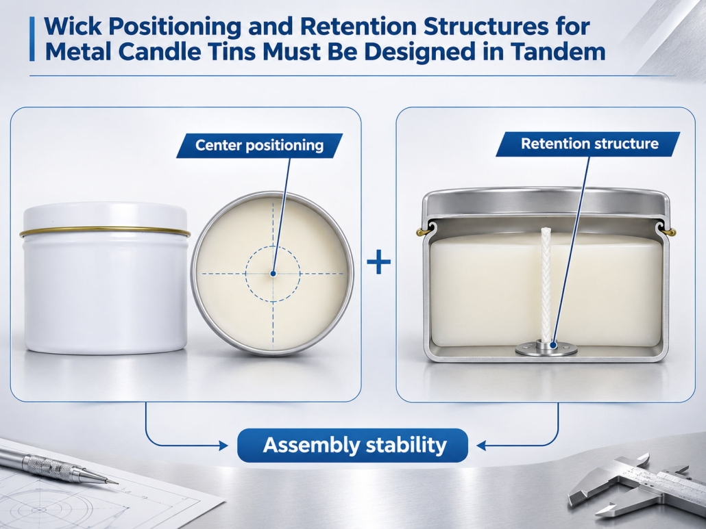
Wick Positioning and Retention Structures for Metal Candle Tins Must Be Designed in Tandem
The wick’s position determines where the flame burns relative to the container wall. Therefore, designers must consider the candle’s diameter and wick layout when designing the securing structure. TSING first determines the required wick positions and then plans how the metal base will accommodate and securely hold each wick component.
Wick Positioning Must Match the Container Diameter and Number of Wicks
For single-wick candles, the geometric center of the container is typically the preferred positioning point. However, manufacturers may need to use multiple wicks in larger containers to ensure the melt pool achieves the desired coverage. The number and placement of wicks should not be determined solely by the container’s diameter. Wax formulations, wick types, fragrance concentrations, dyes, and expected burning characteristics all influence wick selection. Therefore, metal candle tin manufacturers should develop the base layout based on the wick configuration determined by candle manufacturers.
| Candle Configuration | Wick Positioning Consideration |
|---|---|
| Single-wick candle | Usually starts at the geometric center |
| Two-wick candle | Requires symmetrical positioning and controlled spacing |
| Three-wick candle | Requires a balanced layout with appropriate distances between wicks |
| Wide multi-wick candle | Requires coordinated spacing between wicks and the container walls |
In multi-wick designs, an evenly spaced layout helps maintain overall structural balance, but manufacturers must confirm the final coordinates through burn testing. Therefore, TSING recommends confirming the number of wicks, the dimensions of the wick bases, and the center coordinates before finalizing the bottom mold. Engineers can then incorporate these positions into the engineering drawings as fixed reference points.
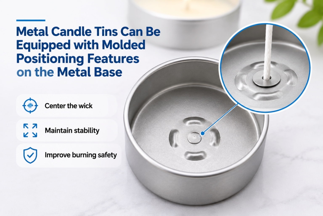
Metal candle tins can be equipped with molded positioning features on the metal base.
One approach is to stamp positioning structures directly into the bottom of the candle tin. These can be shallow grooves, raised positioning points, or a specially designed base intended to keep the wick assembly fixed at all times.
For example, patent US 6,648,631 B2 describes a deep-drawn candle container with a recessed bottom seat for positioning a separate wick holder (patent reference).
For TSING, development focuses on the diameter, depth, center position, and perimeter geometry of the positioning features. The formed area must accommodate the wick base without compromising the flat support surface of the bottom or reducing the effective capacity for molten wax. The primary advantage lies in positioning consistency: the metal tin bottom provides precise alignment for the wick assembly, eliminating the need to rely entirely on manual alignment.
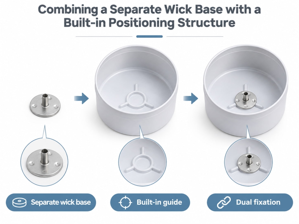
Combining a Separate Wick Base with a Built-in Positioning Structure
Another approach uses a conventional metal wick base (wick holder), crimping it onto the wick and securing it to the bottom of the tin with a suitable adhesive or wick-holding sticker. The base secures the wick, while its neck helps limit how far the wick burns downward. For custom metal candle tins, these two methods can also be combined:
Molded positioning insert → Metal wick holder → Compatible adhesive → Properly positioned wick
The molded positioning insert determines the installation location, while the separate wick holder secures the wick itself. This combination improves positioning consistency while maintaining flexibility when selecting wicks of different sizes or configurations.
Therefore, TSING evaluates whether a project requires only a standard wick-holding method or a structure that combines a specially molded base with a separate wick base. The specific solution depends on the candle’s diameter, wick layout, bottom geometry, and filling requirements.
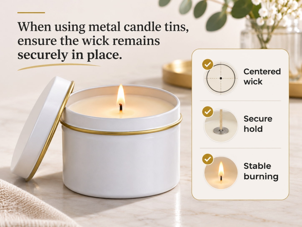
When using metal candle tins, ensure the wick remains securely in place.
Even when workers position the wick holder correctly, the wick may still shift during production. As workers pour molten wax into the container, it may push a loosely secured wick to one side. In addition, poor adhesion, an uneven container bottom, or insufficient top support can all affect the wick’s centering. Therefore, the bottom holder and the wick centering tool must be used together: the bottom holder secures the lower end of the wick. In contrast, the centering tool controls the position of the wick’s upper end during pouring and cooling.
Required Candle Wick Holders and Centering Tools
Before pouring the liquid wax, secure the wick holder to the bottom of a clean, dry container using an appropriate method. During pouring, use a wick centering tool (such as a centering bracket) to secure the top of the wick and keep it vertical until the wax cools and solidifies.
The functions of these two tools differ:
Bottom wick holder: Secures the lower end of the wick.
Top wick centering tool: Keeps the wick vertically centered throughout the pouring and cooling process.
From a manufacturing perspective, we must ensure that the positioning structures formed on the bottom of the tin match the wick holder’s dimensions and that the surrounding area of the tin bottom is sufficiently flat. This ensures customers do not need to make additional adjustments when installing the wick assembly or encounter issues.
Validation Through “Empty tins” and “Finished Candles” Testing
The validation process should be divided into two stages.
First, inspect the empty containers and wick assemblies. Confirm that workers have securely installed the wick holder, positioned the wick as specified, and kept the container bottom stable.
Second, conduct trial production of finished candles. Using the planned wax material, fragrance, wick specifications, and pouring process, verify that the wick remains centered after pouring and cooling. Subsequently, perform the appropriate burn tests on the finished candles to assess whether the wick has shifted or tilted, observe the flame behavior, and inspect the integrity of the container.
The candle manufacturer is responsible for validating the overall “wax + wick” combination. At the same time, TSING focuses on the dimensional accuracy of the candle tin, its compatibility with the wick holder, and structural quality.
Collaborative Design from the Tin Bottom to the Finished Candle
Customizing metal candle tins with built-in wick holders requires coordinating three elements: a practical wick layout, an appropriate positioning structure at the tin bottom, and compatibility with the customer’s filling process. TSING translates these requirements into customized tin-bottom geometries and wick holder mounting dimensions, and validates the container structure through sample development. A candle tin with a built-in wick holder is far more than an accessory added to a metal container; manufacturers must integrate its base geometry, wick position, holder interface, and filling requirements to create a stable, repeatable foundation for candle production.
 Facebook
 Twitter
 Linkedin

